Motogadget's - "Motoscope Mini" installed on the WR250X
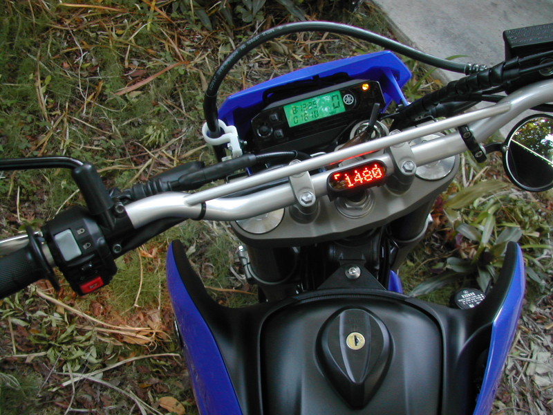
You can read all about it on the Motogadget web site (in the upper right click on Products > Series Mini > Motoscope Mini). Download the manual from their web site and you can see all the settings and adjustments you can make with the Mini. And you can watch this video to see what the Motoscope Mini does. My objective with this page is to simply explain my installation on my WR-X. In the photo below what you see is idle RPM. Above that is a bar graph with a line that moves from left to right as the RPM's increase. Right now I am just using it for a tachometer. After several emails with Heiko at Motogadget Support I came to the conclusion that I didn't want to cut into my OEM speed sensor. I will install the supplied speed sensor at a later date, and eventually get rid of the factory meter all together. This will make room for my next project... an oil pressure gauge.
So first things first. How much was it?
The cost of the Motoscope Mini and the handlebar mounting brackets, including shipping from Germany came to a grand total of $431.97. The Mini comes with an instruction manual, a connector kit to make your own wiring harness plug, a small micro push button to operate the setup menus and change screens. And it also comes with a speed sensor for engines not equipped with OEM speed sensors. The only extra item I had to buy was the handlebar mounting brackets. Both the Mini and the mounting brackets are made of CNC billet aluminum and come either black or silver anodized, or chromed.

Mounting the Mini on the stock handlebars does not leave much of a choice for location. With the crossbar in the way of my riding view, my only choice was to mount the Mini to the rear side of the center. The angle that I mounted it did not require removing the handlebars to tighten the screws. But if you angled the Mini towards the rider more, the screws would be hard to access without removing the bars. They are 3mm allen screws. One screw through each mounting bracket that thread into holes in the back of the unit. They suggest a torque of no more than 4 nm, but not having anything that reads that small I took my chances. I did use some red loctite and snugged them up pretty good. Tighten it until the brackets won't slip on the bars and stop there. To dress up the wire from the Mini, I slipped it inside some old hose I had laying around. It gives it a nice look from the top side and the blue hose matches pretty good with the bike's color.


You can see in the above pic that the mounting brackets are two piece and don't go all the way around the bars. The screws are countersunk and come up from the bottom. I didn't take any photos of the unit and brackets before the install, but you can see from these pics what it looks like.
That was the easy part. Now you have to wire it up. There is a five wire harness coming out of the back of the unit. The wires are ultra TINY and not easy to work with. If you're not into micro surgery you may not want to install this yourself. It took some patience and the right tools. If you're not into small wiring jobs then I would suggest getting somebody with some experience to wire it up for you. Making good connections with small wires is an art. You don't just twist wires together when you're installing something like this.
Remove the headlight assembly and cut the zip tie holding the wiring to the meter so you can access the plugs on the back. Oh, and BTW, you may want to disconnect the battery before you go any further. Just to play it safe.
It's not easy to see all my wiring since I have already taped up some of it, but let me try to explain. It is not that hard, it's just not easy to "T" in tiny wires into an existing system. I used some bullet connectors from work. These are the kind used on Yamaha outboards. I guess you can use whatever connectors you want as long as it's waterproof. These rubber connectors allow for two wires to mate to one. I didn't like the plug connector kit they sent with the unit. Not waterproof enough for me.
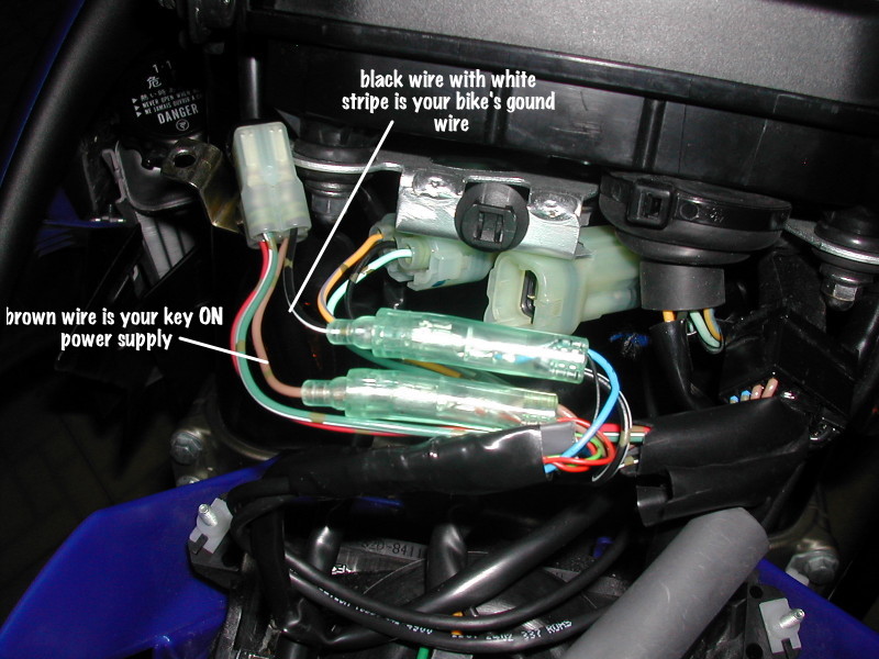
Lets start with the power supply wires. Disconnect the four wire plug on the back of the factory meter. You are going to splice the red (positive) wire from the Mini to the brown wire coming out of this plug. The brown wire is the key ON power supply. 12 volts is supplied to the brown wire when the key is ON. Motogadget does not require a fuse for their unit and say it will run on anything from 7-18 volts. The factory brown wire here is for the turn signals and you will be using that fuse for the power supply to the Mini. This will allow the Mini to turn ON and OFF with the key. Do not connect the Mini's black ground wire at this time.
Now comes the FUN part! You need to install a push button somewhere on your bike to operate the Mini and to access the setup menus. All this is done with one push button. They supply a tiny micro button with the Mini and I decided to make it work for the time being. It is not a water proof button, so if you want something that will last, I suggest shopping around for your own water proof button. Mount it where ever you like. I wanted to have easy access to the button while I was riding so I decided to mount it in the left side switch housing so I could reach it with my thumb, but there is no place to mount it within reach of my thumb. Upon looking at the switch housing a little closer I noticed a small plastic cover that was on the left side next to the grip. If you take the switch housing apart it looks like there were provisions made to mount some sort of switch in the upper area of the housing and possibly this plastic cover I mentioned is where the actual switch is mounted.

I pried off the plastic cover and figured out that the micro push button will fit in this area with a little dremel tool work. I didn't have to hog out much material to make it fit. I also drilled a hole for the button wires to pass though on the curved plastic piece inside the housing. Then route the wires out with the factory wires and to the headlight area. The push button has two wires. One connects to ground and the other to the Mini's green wire. When the button is pushed it gives a ground to the green wire on the Mini and this activates the setup mode and menus and allows you to make the various choices. If you are going to get your own push button it needs to be a momentary push button, not one you push once for ON and again for OFF. You need a button that is ON when pushed and OFF when you let go of it.
Take the small plastic piece you pried out of the left switch housing and drill a hole in it to mount the push button. You will need to take a razor blade and trim off the clip tabs on the back of the plastic piece (if you didn't break them off already trying to get it out of the switch housing) and then use a dremel tool to machine out the back side of the plastic piece so the button will stuck out far enough to mount it with the nut. It was delicate work with the dremel tool, but if you're careful it could be done with a razor knife or some other tool. My photos don't show my machine work very well but maybe you get the idea. The plastic piece is too thick and the nut that holds the button on will not thread on unless you recess the back side of the plastic piece to make it thinner.


Now you need to get yourself a small two wire harness or just use two small wires. Solder one wire to each terminal of the push button and run them through the hole and out with the factory wiring to the headlight area. I used a small two wire harness in my junk pile that came off some old instrument. You can use anything you want, but they need to be small wires. No bigger than 18 gage I would say. So they fit in the small area where the button goes and don't interfere with the handlebars or other switches or wiring. I used a blue and green set of wires. I ran the green wire from the button to the green wire from the Mini. The blue wire will be connected to ground (negative) on the bike and be my ground source for the button. You will need to glue the plastic piece back into the left switch housing once you have the button installed and wired up. I used black silicone to hold it in and keep the water out of the housing. Here is what it looks like once assembled...

Now you need to solve the next problem. When you reinstall the left switch housing back onto the handlebars you will notice the push button hits the shoulder of the left grip. My idea was to be able to activate the button while I was riding remember? With my hand on the grip in normal riding position I do not accidentally hit the button. I poked a small hole in the shoulder of the grip for the button to sit in. This way it is semi-out of the weather and I can still push on the button through the hole with my index finger while riding. It works pretty slick if I do say so myself.


Now go back to the headlight area and look at the four wire factory plug again. The black wire with white stripe coming out of this plug is the ground for the bike. Splice into this wire the black ground wire from the Mini, AND the wire you ran from the button that will be your ground. The other wire from the button will get spliced directly to the green wire from the Mini.
Now would be a good time to check your work so far. You have the red and black wires from the Mini connected and the push button is wired up to ground and to the Mini's green wire. Flip on your kill switch so the fuel pump doesn't run and then turn on your key. The Motoscope Mini should light up and work. You can push the button and scroll through the menus to make sure everything is operating. Now shut off the key and continue with connecting the sensors to the Mini.
At this point you should have only two wires left unconnected from the Mini harness. A yellow wire and a white wire. The yellow wire is for your tach signal and the white wire is for the speed sensor. I got some yellow wire and spliced onto the yellow from the Mini. Now you need to remove the shrouds and fuel tank to access the ignition coil plug. I did it the hard way and just loosened the tank and held it up enough to unplug the coil wire. The coil wire is routed from the coil then forward through an opening in the frame and out to the left side behind the coolant tank. It was not easy, but you can feed the coil wire back forward through the hole in the frame and get enough of it out by the coolant tank so you can cut back the plastic cover and access the coil wires. Take the yellow wire you just spliced to the Mini harness and route it down the left side of the frame to the coolant tank area. Use the factory clips to hold the yellow wire to the frame where the other factory wiring is located. Once you have the yellow wire to the coolant tank area, cut back the black plastic cover over the coil wires to expose them. You will need to splice your yellow wire to the ORANGE wire coming from the ignition coil plug. This is important. DO NOT splice into the red wire of the coil plug. The orange wire will give you a tach signal from the ECU. Make a good water tight connection with your yellow wire to the orange coil wire and tape the black plastic cover back over the wires when you're done. Now gently feed the coil wire plug back through the hole in the frame to the area under the fuel tank and plug it back onto the ignition coil. Reinstall the fuel tank and shrouds.
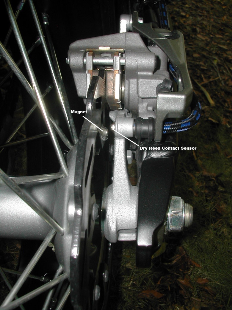
The speed sensor on our bikes puts out a 5 volt signal. The Motoscope Mini manual says it needs a 12 volt speed signal. Motogadget's support guy, Heiko, said my 5 volt OEM speed sensor should work if the polarity of the signal was correct "and" I might have to install the supplied resistor. I wasn't too keen on cutting into the OEM speed sensor and experimenting with resistors, etc... so I have decided to install the 12 volt speed sensor supplied with the Mini. This presented other problems once I got started. First to find a place to mount the sensor. Actually it is called a dry reed contact sensor. A small ferrite magnet comes with the sensor. Once you mount the sensor, you will need to epoxy the magnet to your disc and line it up with the sensor. This particular sensor requires no more than a 5mm gap between the sensor and magnet. Mine worked out to be about a 2mm gap.
After several hours of kibitzing and contemplating, I figured out the best place to mount the sensor was to use an existing hole somewhere. You could make some sort of bracket to mount the sensor, but this looks neater. The rear bolt hole for the rear caliper cover seemed to line up just where I needed it to. The sensor is just long enough to fit through the rear bolt hole and have enough threads on both sides to tighten it in place. I used some spare junk from my "treasure chest" to piece together a spacer and grommet for protection. Ran the wire through the grommet and the caliper cover and mounted the whole thing using only the front caliper cover bolt with some loctite on it. It is fairly solid with just one bolt holding it and there is no tension on the wire or cover. I ran the wire up inside some old blue hose I had laying around and up to the headlight area for connection to the white wire on the Mini.


FYI: The speedometer portion of the Motoscope Mini is capable of being programmed to different wheel sizes. It can also be put into a TEACH mode and "learn" your speed to calibrate itself. There is also a resettable odometer, trip meter and run time mode. And you can set the RPM range to fit your bike's operating range. I have mine set to 0-12,000 RPM since the rev limiter is supposed to kick in at 11,600. You can also set the shift point RPM which makes the entire gauge flash all it's lights when the specified RPM is reached. I set it to 11,000 RPM so it would come on before the rev limiter kicked in. The LED lights in the Mini are adjustable for brightness for both day and night. Once you set the day and night brightness the internal light sensor will switch between day and night automatically.
Copyright 2008 - www.keysdog.com